My Trex Lama did not seem to generate much interest on this forum, it was probably too simple. Maybe this one will be of more interest
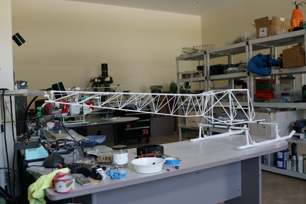
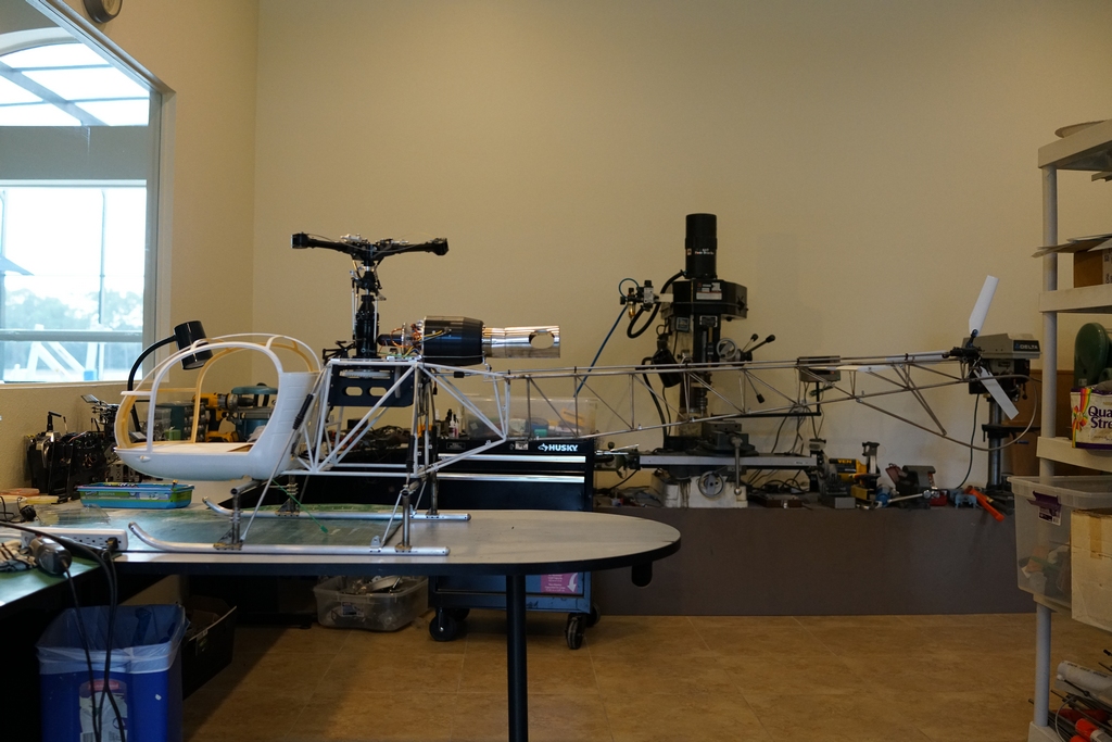
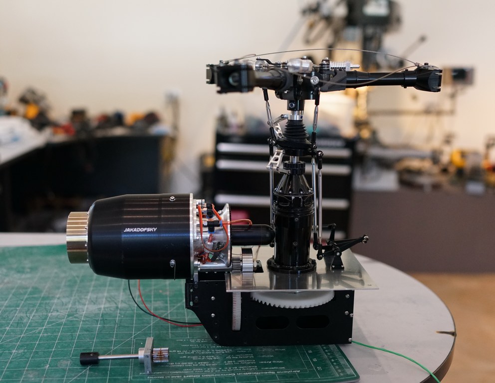
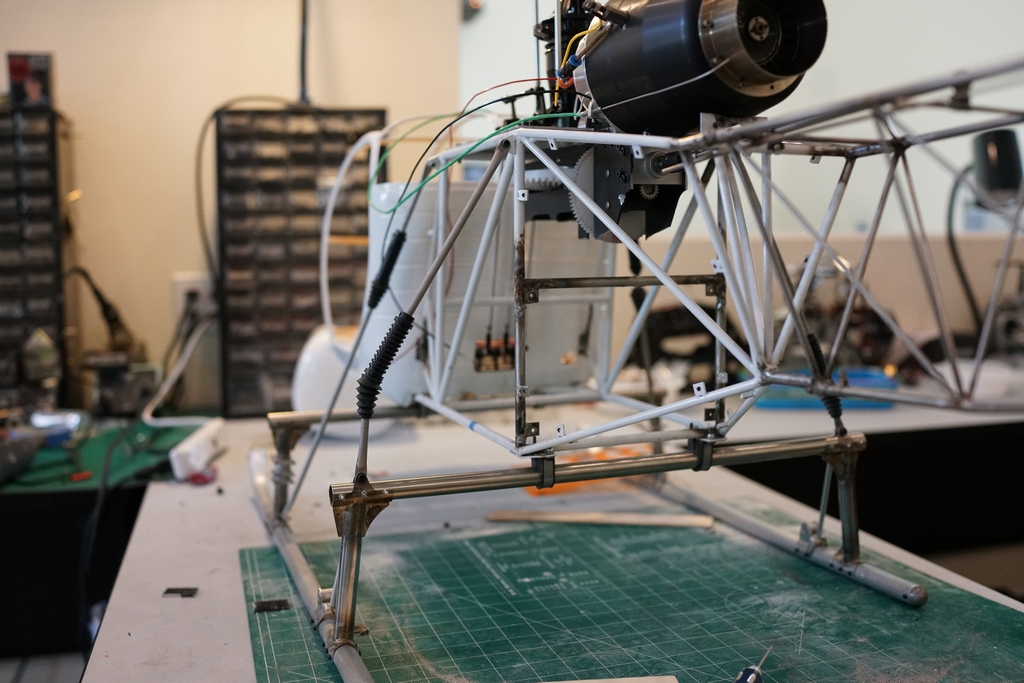
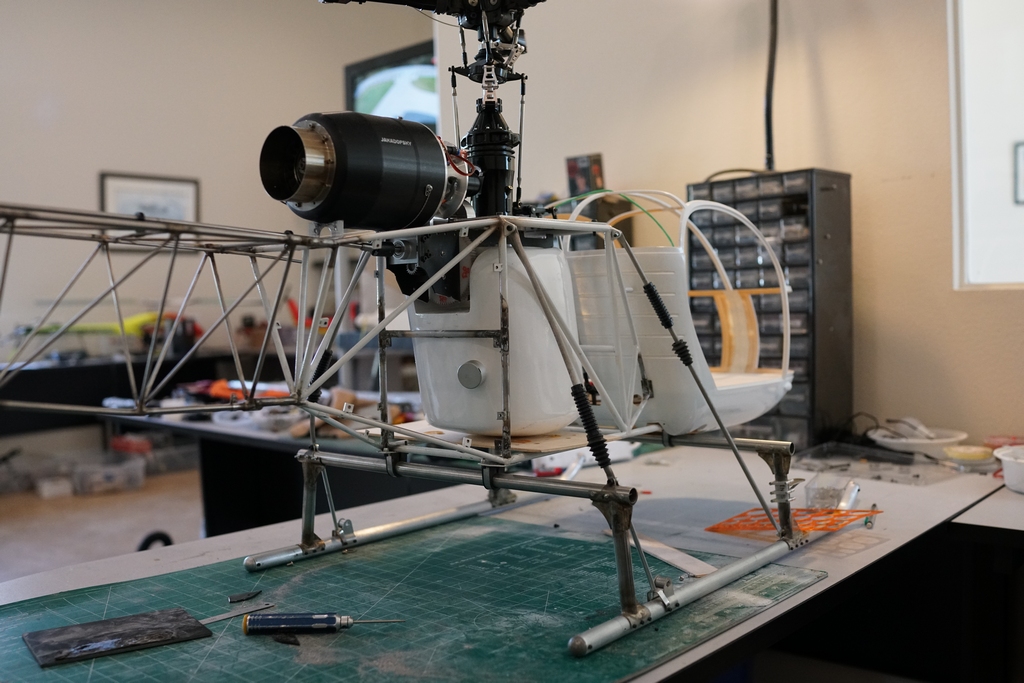
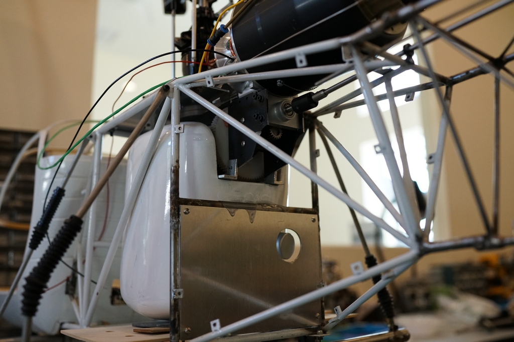
Some time ago I purchased a Hirobo Big Lama with the horrible 35BGX glow engine and a heavy extruded aluminum center chassis. I put it to one side intending to build another tubular center chassis like I did on the Nats Lama. Then one day Joe Howard told me one of the Starwood Lamas I had bought had arrived with a mangled center chassis, so we arranged a new replacement and I got Joe to send the mangled one to me. I repaired the chassis and started the build, but then I discovered I had made a mistake and then the builds with my Grandson Marcus occupied most of my time so the project was shelved. Now I am kind of up to date and back on the hybrid Lama. This is what it looks like so far.
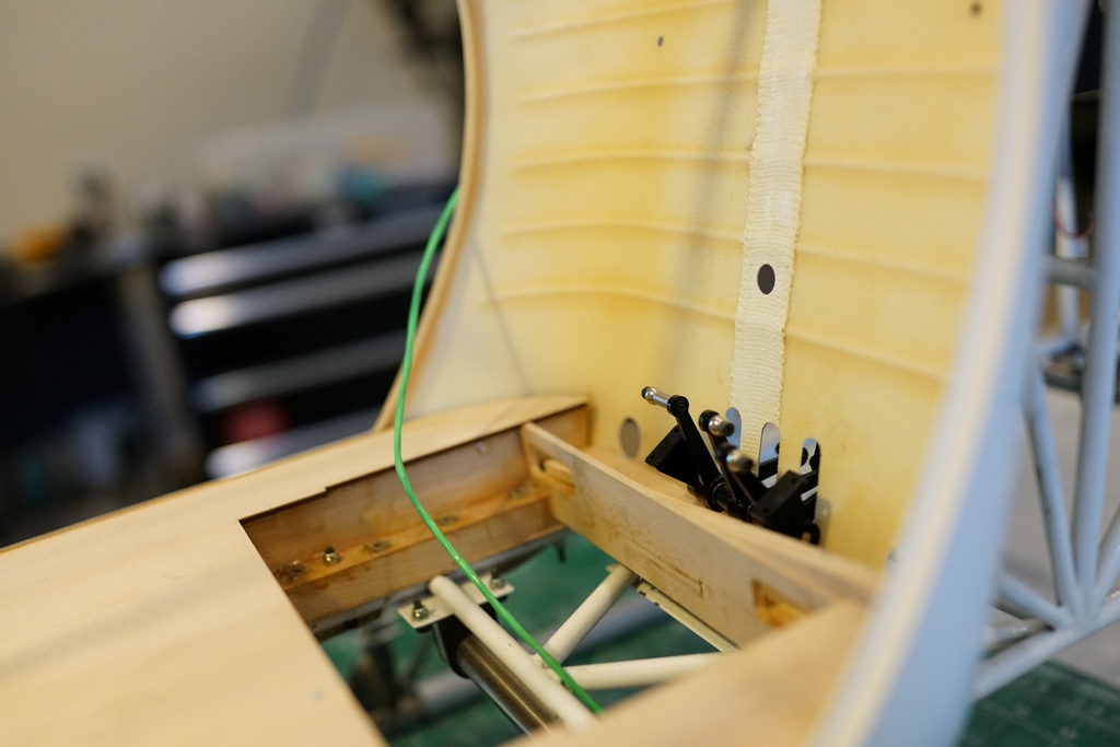
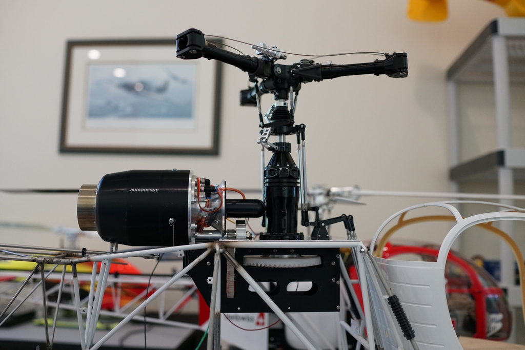
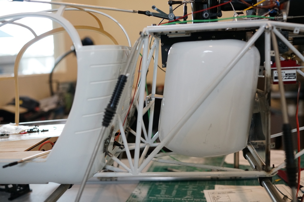
The problem is quite simple. I have machined the custom chassis top plate too far forward. The pushrods from under the cabin foul the back of the cabin.
The Pahl mechanics foul the V tubing at the rear so pushing them back will not be simple
And I forsee a problem mounting the levers and servos in the cabin, but more on that one later on.
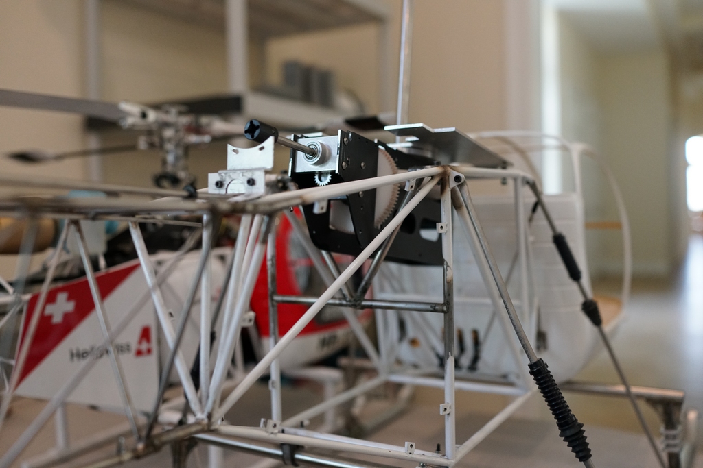
So the job starts by taking the top plate off and making a new one to mount the turbine from. Now I know how it fits, I should be able to make a neater job of it.
With the mechanics out of the chassis, the problem becomes more obvious, as does the solution.
Just make a new top plate which will sit a little further forward! If only it were that easy. I have a top plate which will fit, but there are too many holes in it for glow motor parts etc, but bolting it on temporarily shows the problem
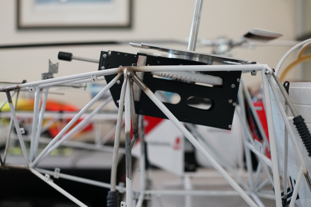
The "V" section at the back, which supports the width of the rear frames by triangulating them, is too narrow.
I am torn between cutting the "V" arms and moving them further out or moving the horizontal crosspiece lower and centering the new "V" arms to keep the rigidity. The top plate will help, but it is bolted to the chassis not welded so there is the opportunity for it to move. More thinking is required.
Having thunk deeply, I decided to simply remove the "V". The cross brace should be adequate and the top plate will help support the frame spacing. So I decided to make a new top plate
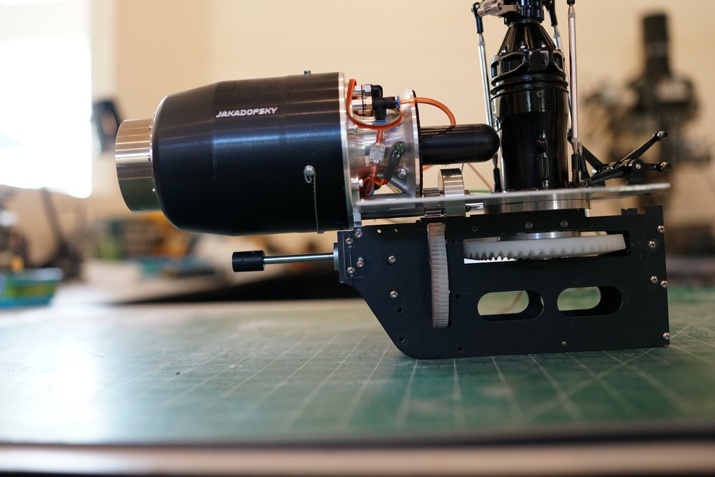
The assembly is complete except for the home made drop down gearbox which needs the shaft shortening now the mechanics are moved back. I cant do that until I have bolted the mechanics into place
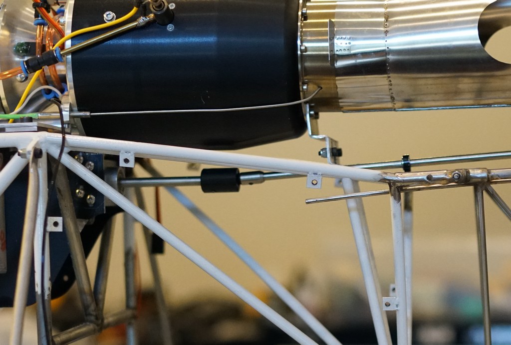
The rear turbine support needs some fettling to clear the turbine case and then I can do the gear box and the turbine rear support. It almost clears the turbine case so a few minutes with a Dremel and flap wheel will have it all shipshape.
The tail drive coupling is done and the mechanics mounted. Everything runs super smooth, I am happy. At least I was until I looked at the servo mounting in the cabin
The kit has this wooden plate for the servos, which should be the old S5050 giant wing servos used in the 90's when this kit was designed.
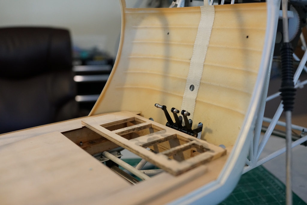
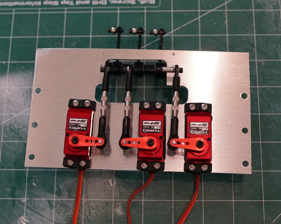
The servos sit on top of the plate and then a nice fiberglass seat covers it all up. My plan is to flip the levers over so they point down not up, make up a metal plate to hold the servos and to mount the servos upside down so the push rods go under the plate and just above the bottom of the cabin. That way I can have a completely flat floor in the cabin. I guess its Miller time, or is that Milling machine time.
This is the bottom of the plate with the levers and arms in place
And installed into position
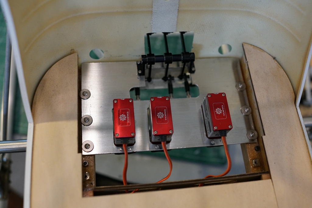
And this gives me another problem. The servos are about 1 mm or so above the level of the floor so I can't make a flat floor. Fortunately I have a solution. The full size I am modeling has a wood floor at the back and the metal painted floor at the front. I will make a plywood floor at the back and cut out the servo holes so they protrude through the floor. Then I will glue some 1/64 ply I have lying around, over the top of the floor to cover the servos.
Next I soldered 4 tabs to the rear frames and drilled and tapped them to hold the back plate
Then I tried fitting the Starwood fuel tank, but the only way it fitted was backward so it sloped the wrong way. I had to get the trusty dremel out and savage the mechanics. I will make up a bottom plate to stiffen the mechanics up as everything is looking a little flimsy right now, even though what i have removed added nothing to the strength of the mechanics.

Now the fuel tank fits nicely, but the filler projects into the back plate, so I am in the process of making a large hole for it to protrude into

Once that is done I can make up some brackets to mount the fuel tank in place.
The hole is drilled and the panel mounted in place. The tank position is critical to avoid the main gear rubbing so I got it set and then dumped a load of PFM over the horizontal brace to secure it.
Once it had set firmly I made up 2 right angle brackets and glued them onto the fuel tank. The brackets extend about 2 " into the tank so it is well secured at the back. Then I made up another bracket to support the front of the tank and glued that into place
Removing the bottom supports and giving the tank a stress test showed it is firmly fixed with nothing underneath it. The PFM peeled off quite easily and left no marks. Wondrous stuff it is to be sure. I rather like the look of it like that but I was unsure if it would stay together. Then I thought about what would happen if the glue broke. Simply, the side braces would hold the tank in place and the bottom braces would stop it falling out. I think its worth the risk to leave it like it is.
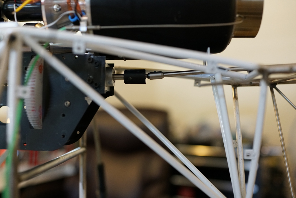
The final job on the pre build was to modify the servo mount for the tail and fix that in position and then test the throws with the 1mm push rod. I was very nervous about that as I did not have another one and if it broke I was in trouble, but I got it all set up before I coupled the last ball link on the servo. I am using a GY601 gyro to stabilize the tail as I wont be fitting a head gyro on this heli.
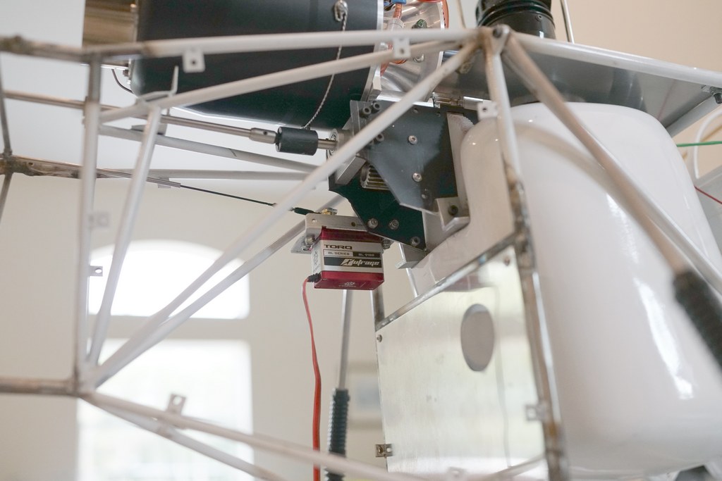
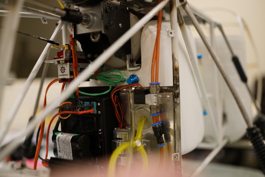
I made up a triangular baseplate to support the on off switch for the turbine and then juggled the parts around to make a nice neat installation.
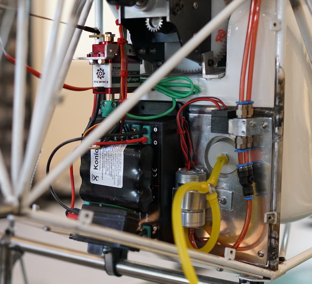
With the turbine battery in the back there will only be two servo type wires going to the cabin, one for the rudder servo and the other for the throttle. Now I have another problem to solve, that of the fuel tank vent/overflow. I had intended to put it in one of the wings but then realized only that wing would fill and the other would be under pressure. I think the only place I can put it will be in the back of the fuel tank roughly where the exhaust temp cable has been strapped up. If I do that, the trick is going to be getting the nipple through the hole without dropping it into the fuel tank. I would normally use a "U" shaped piece of copper wire but I have only done this when the tank was in my hand, not in the model. I may have to take the tank out to do it.
The parts for the fuel tank finally arrived. It must be snowing hard in Oregon!
That's the over flow/tank vent
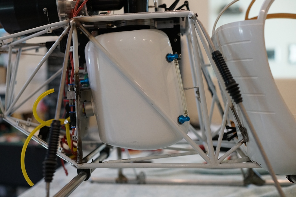
And the sight tube to show me the tank level. I will figure out where to feed the filler line and the vent line later
Thats it for this build for a while. I have to take everything apart and clean all the welds on the lattice and then scrape and clean the powder coating off the Starwood center section. I can see that taking a while as I have other projects on the bench which are shouting at me, including trying to get my Grandsons Cobra in the air. I bought it from Align and one of the major parts is missing so he cant complete it. Very disapponting.
When I said it would be a while, I really didn't think it would be this long, but it is finally back from powder coating. I must admit, my flight testing took a lot longer than it should, these models are just a delight to fly and I kept flying it until I finally used up all my kerosene. Then I took it apart and that meant a few changes, particularly to the fuel tank as the overflow outlet stopped the tank from coming out. Anyway, all if fixed now and reassembly can begin.